
Royal Enfield
Himalayan 450
How to perform a complete engine overhaul?
Translating technical record...
A complete engine overhaul on the Royal Enfield Himalayan 450 requires removing the engine from the chassis, completely disassembling the top-end, side covers, and crankcase, measuring and renewing worn components, and methodically rebuilding both the bottom-end and top-end.
1. Preparation & Engine Removal from Frame
▼
- Allow the motorcycle to cool completely, park it upright on a level surface, and fully drain the engine oil and coolant (49) (213).
- Remove the pillion and rider seats (49) (50).
- Disconnect the negative battery terminal followed by the positive terminal (50).
- Depressurize the fuel system, disconnect fuel pump/gauge electrical connectors, EVAP and drain lines, and remove the fuel tank (50) (51).
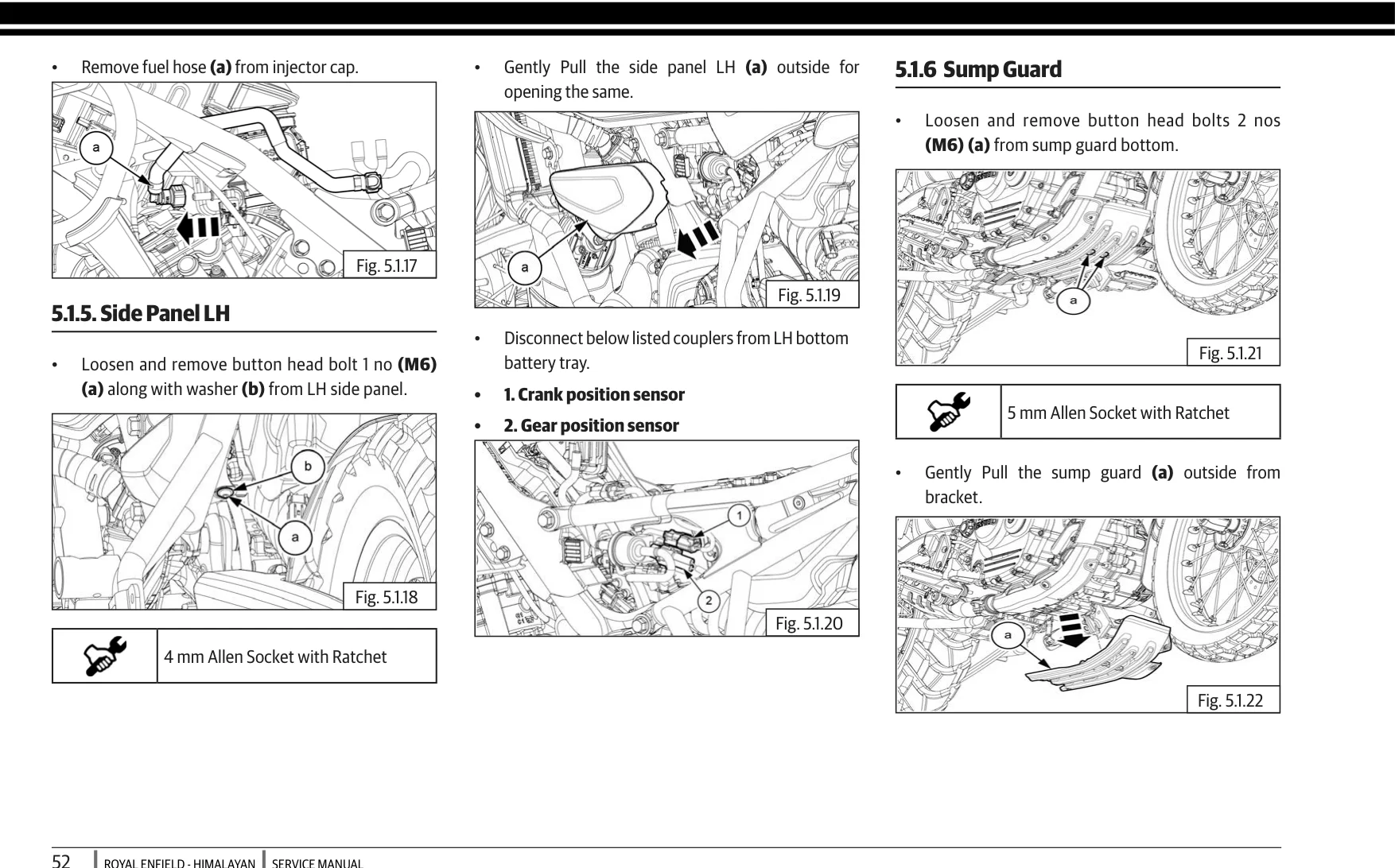
- Disconnect engine electrical harnesses (crankshaft position sensor, gear position sensor, injector, ignition coil, sensors) and remove the air filter box (52) (213).
- Disconnect the exhaust system, throttle body, clutch cable, drive chain, cooling hoses, and radiator (235).
- Support the engine using an Engine Mount Fixture (ST32064/A) and remove the mounting bolts to drop and extract the engine unit from the main frame (42) (47).
2. Top-End Disassembly
▼
- Remove the cam cover (3 M6 bolts with seal washers) and gasket (213).
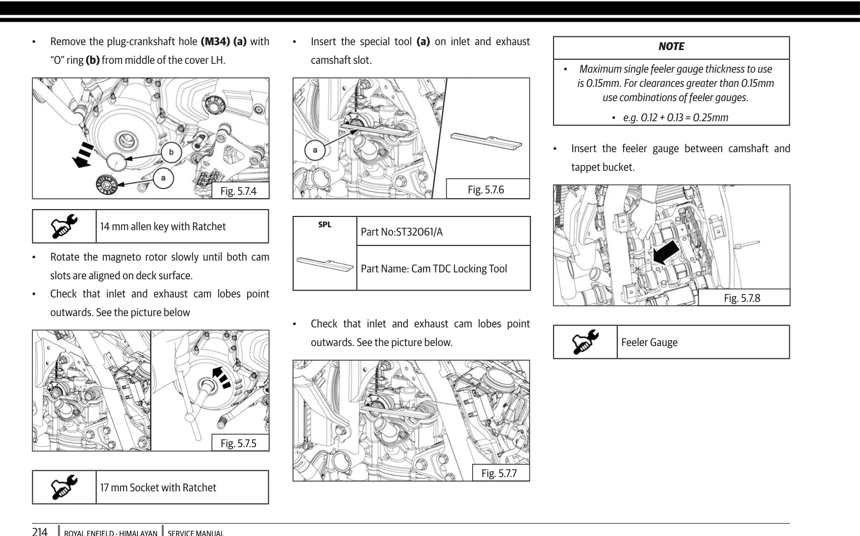
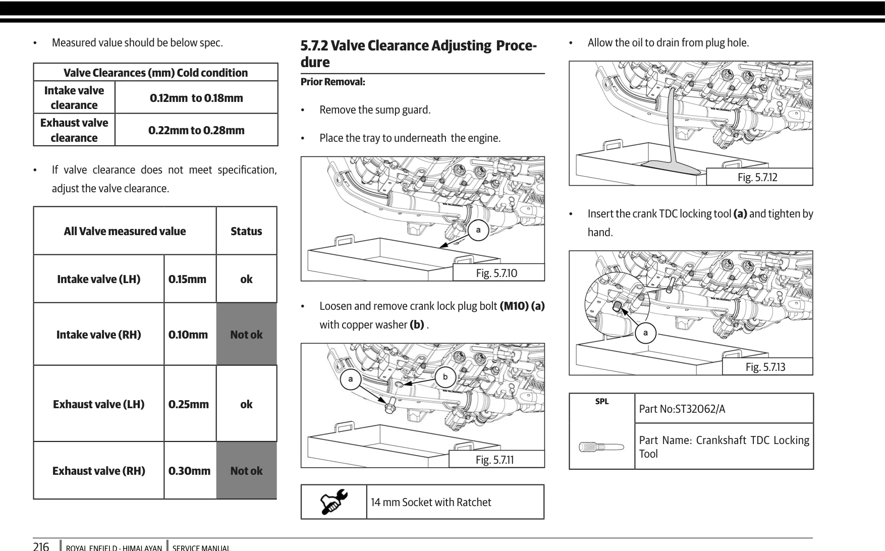
- Remove the crankshaft access plug (M34) on the LH cover, rotate the engine to Top Dead Centre (TDC), and lock the crankshaft using the Crank TDC Locking Tool (ST32062/A) (106) (216).
- Remove the Hydro Mechanical Tensioner (HMT) from the RH side of the cylinder (107).
- Remove the top cam chain guide plate, cam sprockets (M8 bolts), cam ladder caps (M6 bolts), dowel pins, and camshafts (106) (108).
- Extract the bucket tappets and shims with a magnetic tool, noting their exact positions (109) (218).
- Loosen the 2 outer M6 head bolts and the 4 main M10 head bolts in a crisscross pattern; remove the cylinder head and gasket (109) (110).
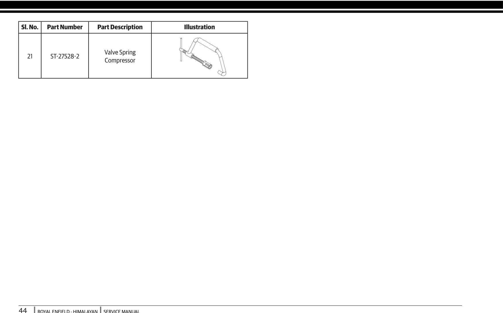
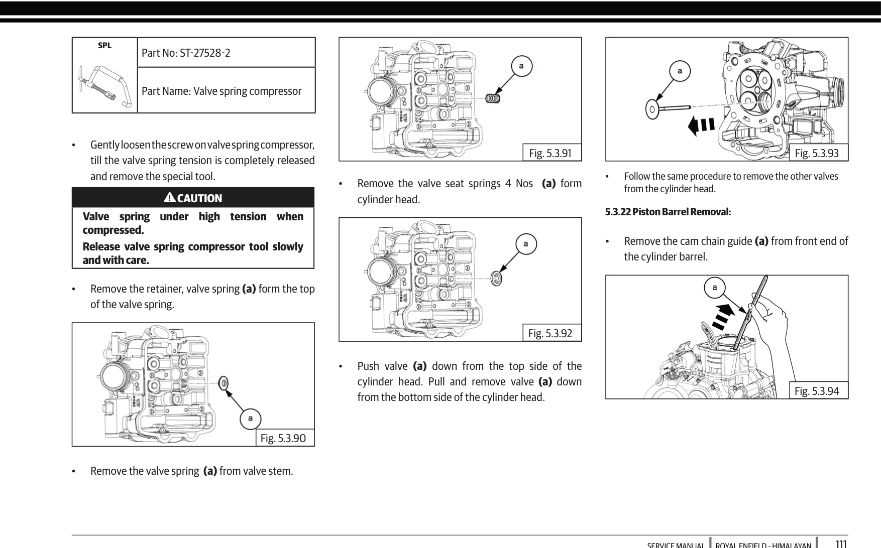
- Compress the valve springs using Valve Spring Compressor (ST-27528-2) to extract the cotters, retainers, springs, seats, and valves (44) (110).
- Pull the cam chain guide rail out, lift off the cylinder barrel, remove the piston wrist-pin circlips, and slide out the gudgeon pin to free the piston (111) (112).
NOTE Cylinder head bolts are one-time use only. Always replace them with new bolts upon reassembly (110).
3. Side Covers & Bottom-End Disassembly
▼
- LH Cover (Magneto/ACG): Remove the ACG cover. Using Magneto Holding Tool (ST32065/A) and Magneto Puller Assembly (ST30274/a), remove the rotor/flywheel and starter drive gears (42).
- RH Cover (Clutch & Oil Pump): Remove the clutch cover. Hold the clutch with Clutch Holder (ST30266/a), disassemble the clutch spring plate, pressure plate, friction/steel plates, clutch center hub, and basket (42) (237).
- Remove the primary drive gear, gear shifter shaft mechanism, and oil pump assembly (43) (231).
- Crankcase Splitting: Remove all crankcase joining bolts evenly in a crisscross pattern. Separate the crankcase halves using a soft mallet (37).
- Remove the gear shift forks, shift drum, countershaft assembly, and driveshaft assembly (43) (141) (144).
- Remove the crankshaft and balancer shaft assemblies from the main journal bearings (232) (236).
4. Inspection, Cleaning & Component Measurement
▼
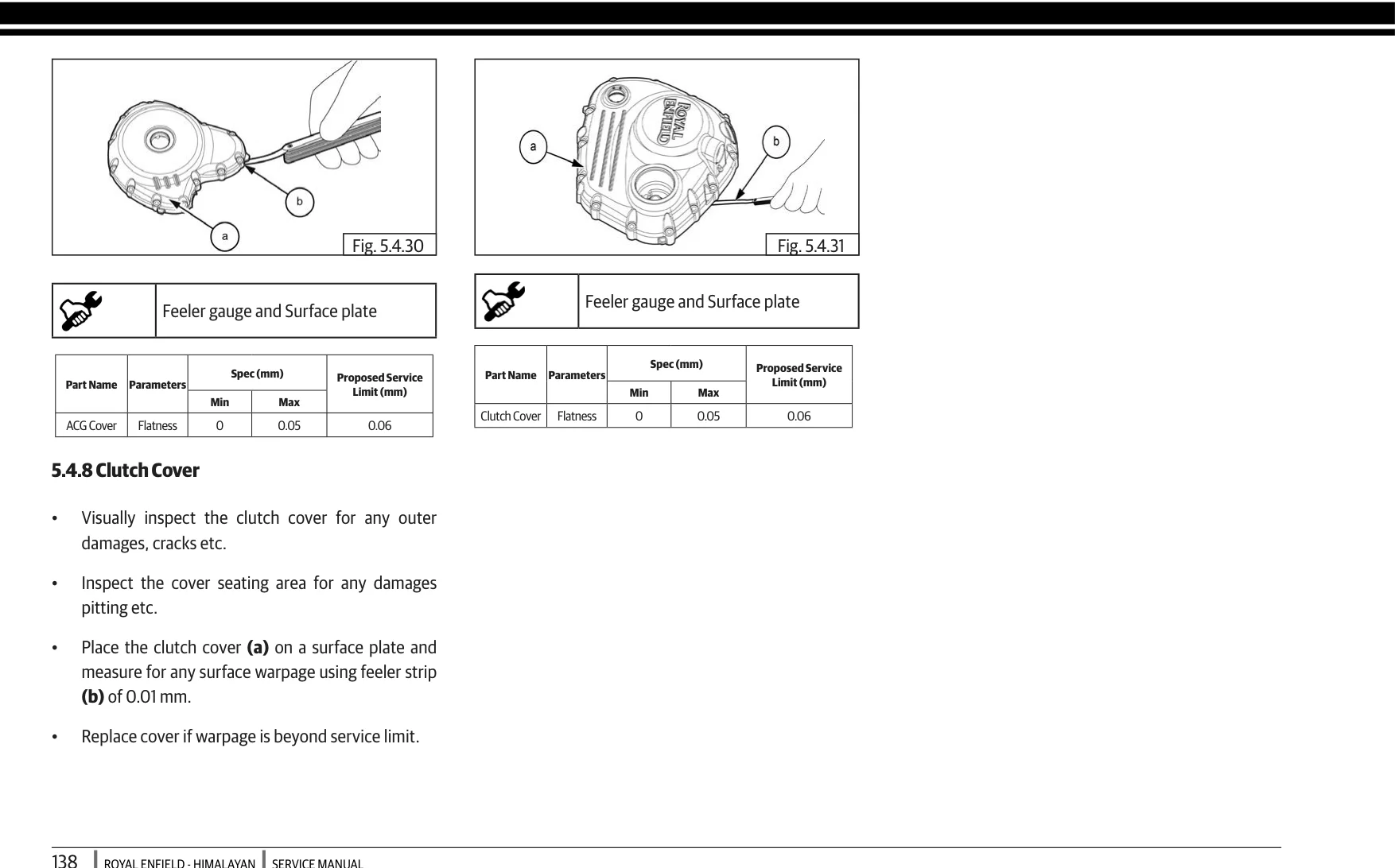
- Surfaces & Warpage: Inspect mating surfaces of the cylinder head, barrel, clutch cover, and ACG cover on a surface plate with feeler gauges (service limit: 0.05–0.06 mm) (138) (229).
- Cylinder & Piston: Check cylinder bore for scoring, ovality, and wear; measure piston ring end-gap inside the bore; inspect piston skirts for scuffing (229) (234).
- Valves & Guides: Measure valve stem runout and guide clearance; discard old valve stem oil seals (228) (233).
- Bearings & Shafts: Inspect crankshaft, connecting rod big-end, and balancer shaft journal bearings for wear or scoring; cross-reference color codes for shell replacements (235) (236).
- Transmission: Check gears, dog teeth, bushes, and splines for pitting or wear; replace all transmission circlips and thrust washers (142) (144) (238).
5. Reassembly: Transmission & Crankcase
▼
- Transmission Reassembly: Reassemble the countershaft and driveshaft gears, lubricating gear bores and splined bushes with GL 80W-90 oil. Ensure circlips are correctly oriented and fully seated in their grooves without over-expanding (141) (142) (144).
- Fit the crankshaft, balancer shaft, and transmission shafts with shift drum and selector forks into the crankcase half (141) (236).
- Clean crankcase mating faces, install dowel pins, apply a thin, uniform bead of three-bond liquid gasket, mate the crankcase halves, and torque all case bolts in a crisscross sequence (verify specific torque values with workshop manual).
- Install the gearshift mechanism, oil pump, and primary drive gears (43) (231).
- Rebuild the clutch assembly, install the clutch outer cover, rebuild and install the magneto/flywheel, and fit the LH cover with a new gasket (42) (138).
6. Reassembly: Top-End & Cam Timing Setup
▼
- Piston & Barrel: Install new piston rings with staggered end gaps. Fit the piston onto the connecting rod using a new wrist-pin and fresh circlips. Fit a new base gasket and dowel pins, compress the rings, slide the cylinder barrel down over the piston, and install the front cam chain guide (111) (112).
- Cylinder Head: Fit new dowels and a new head gasket; position the head, install new M10 head bolts, and torque in a crisscross sequence followed by the M6 bolts (verify step-torque sequence with workshop manual) (109) (110).
- Reinstall valves with new stem seals, springs, retainers, cotters, original shims, and bucket tappets (109) (111) (233).
- Timing & Tensioning:
- Lock the crankshaft at TDC with Crank TDC Locking Tool (ST32062/A) (216).
- Reinstall camshafts, cam ladder, dowels, and O-rings, tightening ladder bolts evenly (107) (108).
- Mount the cam sprockets and align marks with cam lobes facing outward (106) (214).
- Install the HMT with a new sealing washer and torque to 38 – 42 Nm; push the chain guide using the Nylon Rod Tool (ST32070/A) until the tensioner clicks out of its transit position (42) (224).
- Verify timing alignment using Cam TDC Locking Tool (ST32061/A) (42) (224).
7. Valve Clearances, Engine Installation & Fluids
▼
- Check cold valve clearances using feeler gauges (214) (216):
- Intake: 0.12 – 0.18 mm (216)
- Exhaust: 0.22 – 0.28 mm (216)
- Adjust shims if out of specification: $\text{New Shim} = \text{Current Shim} + \text{Measured Gap} - \text{Specified Gap}$ (215).
- Remove the crank TDC tool and torque the M10 crank locking plug with a new copper washer to 18 – 22 Nm (225).
- Reinstall the M34 crankshaft access plug with a new O-ring (torque to 30 – 34 Nm) (225).
- Fit the cam cover with a new gasket and tighten the 3 bolts with new seal washers to 11 Nm (225).
- Remount the engine into the motorcycle chassis and torque all engine mount bolts (34) (47).
- Reconnect all throttle bodies, intake manifolds, exhaust pipes, wiring connectors, cables, drive chain, and radiator hoses (52) (235).
- Reinstall the airbox, fuel tank, battery cables, and seats (50) (226).
- Fill the engine with ELF Moto 4 Roadstar 10W-40 (API SN / JASO MA2) engine oil (226).
- Fill and bleed the cooling system with Total Coolelf Auto Supra -37°C coolant, run the engine to operating temperature, verify fan operation, and inspect for leaks (209) (232).
Information Sources
Verified Technical Data: Grounded directly in the official OEM Workshop & Owner's Manuals with exact page citations.
Himalayan 450 Service Manual
pages: 34, 37, 42, 43, 44, 47, 49, 50, 51, 52, 106, 107, 108, 109, 110, 111, 112, 138, 141, 142, 144, 209, 213, 214, 215, 216, 218, 224, 225, 226, 228, 229, 231, 232, 233, 234, 235, 236, 237, 238












💬
Comments
(0)
Write a comment...